May Technical

FlapGate
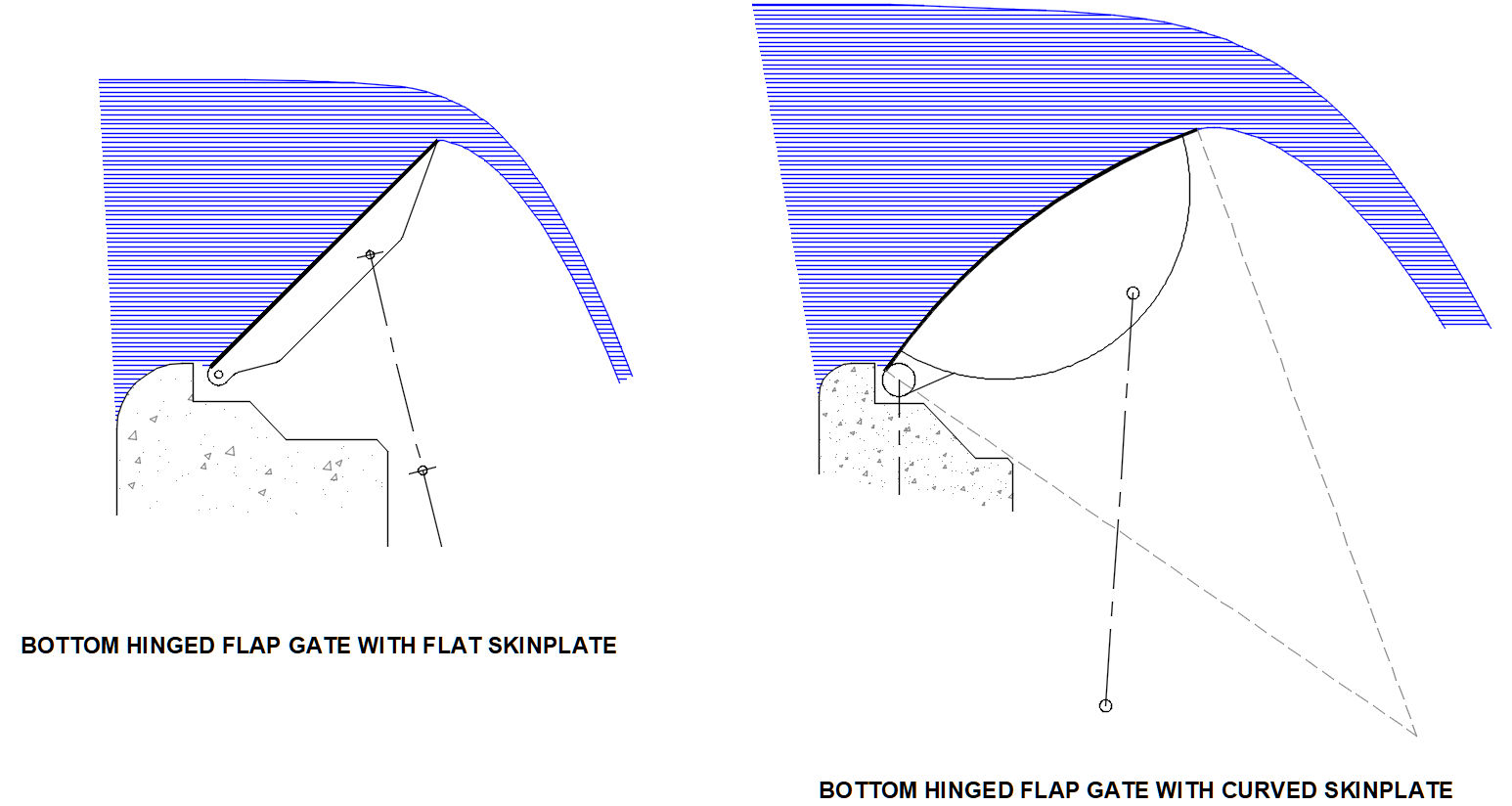
This Flap Gate Design program provides a preliminary design analysis for bottom hinged flap gates that have either flat or curved skinplates. It is emphasized that this is a "preliminary" design that concentrates on flow over the gate as well as moments and loads on the gate. Flap gates are overflow type gates that are often used to provide flow control at dam spillways. They have the unique advantage that debris and ice can be easily passed with small gate openings. However, they are particularly difficult to design using manual methods. A hydraulic model or CFD is usually used to determine flows as well as hydraulic loads. A finite element analysis is then mandatory to explore all load combinations and resulting stresses. Consequently the design provided here is considered "preliminary". However, the Excel spreadsheets provide a good estimation of flow and forces for the purpose of feasibility or initial design. Microsoft Excel workbook is used so that operation is both familiar and easy. Visual Basic macros are used where needed.
Design
The flap gate assembly comprises a flat or radiused upstream skinplate that is stiffened from behind. A curved skinplate usually has a curved downstream plate such that a flattened tube is formed which provides an optimal torsional resistant structure for larger or longer gates. The structural design of the gate is not included here since a finite element analysis is preferable.
The following two references are key to the determination of flows and forces at various gate positions:
1. "Hydrodynamic Forces" by Eduard Naudascher; IAHR Hydraulic Structures Design Manual 3
2. "Lock Gates and Other Closures in Hydraulic Projects" by Ryszard Daniel & Tim Paulus
The first reference is used to estimate flows and forces (moments, horizontal forces and vertical forces) from various graphs in Chapter 4. Figure 5.24 of the second reference gives the distribution of hydrostatic pressure.
Each gate is hinged at the sill by a minimum of two gate bearings. If more than two bearings are used then all bearings need to be accurately aligned to minimize minimize unnecessary misalignment forces. It is assumed tht the gate is operated by hydraulic cylinders mounted underneath the gate on the downstream side. Alternatively, it is possible to mount hydraulic cylinders above the gate at each end which implies two cylinders per gate. Hydraulic cylinder and bearing pressures are calculated so that the number of cylinders and bearings can be determined.
Since this is a preliminary design the Excel spreadsheet is NOT protected from alteration. The origin of all calculations can be seen and the user can make any changes they see fit. This is done so that the spreadsheet can be customized for each application. Please kindly use the "Contacts" tab to let me know of any improvements that you make, as a courtesy, considering the amount of work that went into preparing this Excel spreadsheet.
User Input
