May Technical

VertGate
This Vertical Lift Gate Design program provides a comprehensive design analysis for vertical lift gates with the minimum amount of effort. The program encompasses many different design options and provides a conservative design. The latest version is written using Microsoft Visual Basic 6 which makes operation fast without the overhead coding of Excel.
Design
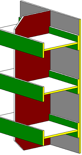
The vertical leaf gate assembly comprises a number of horizontal girders welded to end members designed to transfer hydrostatic and seismic loads to embedded guides. The skinplate is considered to be an integral part of the girders with the whole assembly being stiffened vertically by diaphragms as necessary.
The spacing of the girders on the gate is optimized by the program, or, may be entered manually. The size of the girders may be user entered, or, selected from an AISC database of standard beam shapes and sizes.
Hydrostatic and seismic loads are considered in the design. Seismic loads act on the gate during an operational basis earthquake (OBE) resulting in horizontal acceleration. The Westergaard formula is used to determine the added water pressure on the gate.
Allowable strength design methods are used per AISC 360-22 Specification for Structural Steel Buildings. Standard beam shapes are taken from AISC Shapes Database Version 16.0. For normal loading conditions, the allowable strengths are multiplied by a user definable design factor based upon recommendations from the Corp of Engineers EM 1110-2-2105. Also reference EM 1110-2-2701.
For fixed-wheel gates the roller assemblies are also designed using the program. Crowned rollers and their axles are fully designed in accordance with criteria outlined by Skinner's "Fixed-Wheel Gates for Penstock Intakes". The design of rollers, bearings, axles and their supports take into consideration the lateral load acting on the roller due to possible roller misalignment. Wheel axles may be cantilevered from the end of the gate or supported at each side of the wheel by vertical end members.
Results
Beam section properties are calculated based upon the information provided. These properties are determined in accordance with AISC. The nominal strengths are calculated and take into consideration compression and tension flange yielding, lateral torsional buckling and compression flange local buckling. Stresses are determined and compared to allowable stresses in general accordance with AISC requirements. All significant calculated results are highlighted in red where not acceptable.
Operation
Side, lintel and sill seals are designed including frictional loads that affect gate operation. Gate operating loads are determined from gate volume, weight and center of gravity based on the dimensional data provided. The downpull on a vertical lift gate is also considered with the gate at partial openings. Downpull applies to a submerged fixed-wheel gate with a downstream lintel seal and downstream skinplate under flow conditions. Calculation of downpull is per "Hydrodynamic Forces" by Naudascher. Hoisting loads are calculated for a range of gate positions both for gate lifting and lowering.
Changes for 2025
The program is now coded using Microsoft Visual Basic 6 instead of Microsoft Excel. This reduces a lot of the overhead coding required by Excel. The program uses a sequence of forms to both enter information and display results. The program is "stand alone" and is an unalterable *.EXE file. Gate projects are saved as a individual data files with the *.GAT extension that may be saved or loaded into the program as required. Each GAT file contains only project data. Each form of the program may be saved using the SCREENSHOT button. These screen shots are in *.BMP format and can be combined using Adobe Acrobat. The final form shows a PRINT button that can be used to create a *.TXT file giving all the inputs and design results in a presentable format. Each form has a HELP button that provides context sensitive help. Select a variable and press HELP. A User Manual is not then required.