May Technical

RadGate
This Radial Gate Design program provides a comprehensive design analysis for radial gates with the minimum amount of effort. The program provides a conservative design for gates with two or three arms in accordance with Corp of Engineers Manual EM 1110-2-2702 and ETL 1110-2-584. Microsoft Excel workbook is used so that operation is both familiar and easy. Visual Basic macros are used throughout to facilitate design.
Design
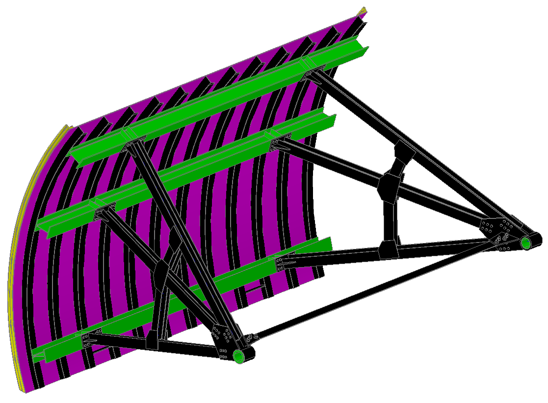
The radial gate assembly comprises a curved skinplate backed by a number of vertical stiffeners attached to two or three horizontal girders, to which radial arms are connected. The arms are joined by vertical steel plates welded to the trunnion hubs. The assembly transfers load to the trunnion bearings and thence to the trunnion pins embedded in the pier walls.
Hydrostatic, gravity, ice and seismic loads are considered in the design. Seismic loads act on the gate during an operational basis earthquake (OBE) resulting in horizontal acceleration. The Westergaard formula is used to determine the added water pressure on the gate. The design considers a user definable ice load applied near the top of the gate.
Load and Resistance Factor Design (LRFD) methods are used per AISC Manual of Steel Construction - 13th edition using seven load cases in accordance with the Corp of Engineers Manual.
Trunnion bearings may be either cylindrical or radial type and supported on a cantilever or double support. A trunnion brace may be specified to prevent lateral splay of the arms. Radial type bearings may be selected to compensate for misalignment of the trunnion arms.
Results
All section properties are calculated based upon the information provided. Nominal strengths are calculated and take into consideration compression and tension flange yielding, lateral torsional buckling and compression flange local buckling.
Finite element analysis is used to determine the moments and loads for each girder frame formed by a horizontal girder and two arms. Lateral displacement of each girder frame is also considered for the case where the gate twists during one sided operation. Finite element analysis is also used for design of arm frames and for vertical trusses. Gate twisting may be resisted by the skinplate corners, bumpers or rollers. Bumpers or rollers are located at the ends of the top and bottom horizontal girders.
Side seals are designed including frictional loads that affect gate design and operation. Gate design and operating loads are from gate weight, seal friction and trunnion friction. Hoisting loads are determined. All significant calculated results are highlighted in red where not acceptable.
